DTW gas flue systems
Developed in cooperation with Meisterwerke Autosport
There is no substitute for displacement - except more displacement!
Who hasn't heard this oft-repeated quote? And how true it is - but more on that elsewhere!
Unfortunately, the performance optimization of naturally aspirated engines cannot be achieved with a simple data set or simply by replacing the "downpipe" with flow-optimized catalytic converters, as is the case in today's turbo era. A little more boost pressure here, a little fewer cells in the catalytic converter - and we have a simple recipe for more power. No, unfortunately it's not that simple with air-cooled six-cylinder engines - and that is precisely our challenge.
Suction engines
If you want to get the most out of your air-cooled six-cylinder engine, you have to take a more informed approach.
It is no secret that popular measures such as an increase in displacement, cylinder head modifications, increasing the compression ratio, changes on the intake side, map optimizations (with electronic engine control) and, above all, replacing the exhaust system are the first choice.
Interpretation
Over the past few years, we have set ourselves the challenge of getting to the bottom of the technical mechanisms of this "legendary thing".
The basis of our development is a small, self-written calculation software that uses empirically determined formulas to precisely determine the target variables for charge change optimization. In concrete terms, this means: pipe lengths, diameter, type of manifold geometry, silencer design, etc.
In order to function optimally, a fan manifold sports exhaust system must take into account engine-specific characteristics such as displacement, timing - in particular the timing of the valve overlap - and a defined operating point. Secondary, but no less important, are the pipe routing, the geometry of the manifold and small special features such as the diameter jumps (so-called "steps"): more on this later!
In theory, there are fluid mechanics formulas that can be used to design the pipe dimensions. In addition, empirically determined parameters, i.e. formulaic relationships validated on the test bench, can be found after a thorough literature search, which allow the fluid mechanics to be optimally determined.
To develop the exhaust system, we took a close look at all of this documentation, some of which was "historical", and transferred it to a calculation tool. For us, this calculation method forms the basis for a design that is optimized in terms of performance and torque.
We were already able to carry out performance measurements on the first prototypes in 2015, which led to a torque peak of 365 Newton meters and over 318 hp. This was measured on a 3.6-liter engine with modified Motronic and a 304° Schrick camshaft at a compression ratio of 11.5 : 1.
In addition to determining the correct pipe diameters and pipe lengths, we have implemented a further fluid mechanical optimization. Our manifolds have a wall thickness step in the primary pipe after a defined length. This involves a little more effort in terms of production, but pays off in an overall increase in the torque and power band. In theory, this jump, also known as a "step", ultimately has the same effect as a correctly selected primary pipe length - namely a reduction in the pressure in the exhaust gas through a so-called induced pressure wave. This is reflected at the "open end of the pipe" and helps the engine to achieve a more efficient filling with fresh gas through the so-called "pulse tuning" effect.
In short, this creates a charge change optimization. According to the ideal design, the "returning" vacuum wave should be in contact with the exhaust valve at the time of valve overlap in order to bring additional suction/vacuum into the combustion chamber when the exhaust is opened (AÖ), thereby ensuring the charge exchange optimization described above through more efficient scavenging and faster fresh gas flow. This theory must be validated in practice by a number of test bench runs, even if the theoretical design is very sound.
Quality
Where the challenge was not only to maximize the power output but also to achieve a balanced sound, an ideal technical integration into the engine compartment had to be achieved.
Our mission from the very beginning was to deliver maximum quality to our customers.
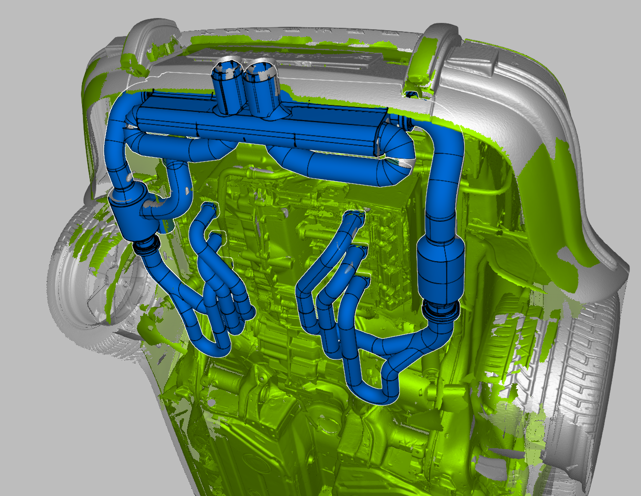
We have chosen a very complex computer-aided development process for this.
Using 3D measurement with our Artec photogrammetry scanner, we created a three-dimensional, virtual computer model of the complete vehicle, in particular the engine compartment.
A CAD design was created on the basis of this installation space model, which was integrated without touching neighboring components or being too close to heat-sensitive components (such as a drive shaft sleeve or oil lines).
Another advantage is that we had all the components of the exhaust system available as a virtual data model and were therefore able to guarantee fully CNC-supported production of the individual parts. The silencer covers are first laser-cut from a stainless steel blank and then bent into shape on a CNC press brake. This means that one component is later exactly like the other.
For the sound-absorbing components, we use a special glass fiber insulation mat in combination with a non-magnetic stainless steel mesh. These materials both have a high-temperature specification and are heat-resistant up to 1200° Celsius. The origin is actually Germany, so we can trace the supply chain and quality.
In this way, we ensure that the system remains within the legally permissible noise limits even after many years of operation.
The pipe bends are partially pressed and therefore manufactured with high-precision internal and external dimensions. The primary pipes are CNC-bent, while all other pipe sections, such as the header, are 3D CNC-lasered by a partner.
We can also use this production method to manufacture medium-sized quantities in a relatively short time.
The individual parts are first TIG-welded according to a defined work sequence (heat stress-optimized welding sequence) and later joined together to form a complete system during the assembly of all individual parts using three separately measured gauges.
The final production step is the completion of the entire system on a gauge that takes into account the subsequent assembly situation on the vehicle. This means that we make final gauges for the six outlet flanges and the mounting position before delivery. The advantage of this is that each system can be installed by the customer straight from the box without any reworking.
All necessary assembly materials, some of which we have developed ourselves (some of which replace original parts), are supplied with the delivery, for example our "spacer system" for fine adjustment of the rear silencer position on the new stainless steel engine cross member supplied.
Performance
The two 200-cell catalytic converters come from HJS. We deliberately decided against 100-cell catalytic converters - based on the recommendation by HJS to use 200-cell catalytic converters. We can therefore ensure maximum longevity.
The difference between 100 cells and 200 cells in the catalytic converter is measurable in the peak power - but not across the board. This is engine-specific, but an order of magnitude here is between three and five hp from our own experience.
Due to the "Euro 2" emission requirements, which are not easy to meet, we decided to make this compromise in favor of higher quality and maximum longevity in the interests of the customer.
According to many confirmed dynamometer measurements, the system is capable of delivering outputs of between 315 hp and over 400 hp with 3.6/3.8 and 4.1-liter engines. It must be mentioned here that, due to specific engine/component tolerances and/or changes to the camshafts, compression, throttle valve and other components, each engine does not allow any serious general statement to be made as to what "final output you will end up with". However, we can assume that, in conjunction with a lambda map adjustment, additional outputs of between 35 and 45 hp are realistic. We have already measured these values (and even much higher ones) several times in real life - below is a test bench protocol of Falco's 1991 Carrera 2 3.6 liter. The hardware changes are noted on the test report.
Our exhaust systems have also been tested several times in practice on various circuits.
The specific challenge is to withstand the extreme demands of high full load proportions over the long term.
Some racetracks do not allow the operation of vehicles that are too loud. One example of this is the BILSTER BERG. In 2021, we were able to stay below the permitted decibel limit during a video shoot with two vehicles equipped with our exhaust systems. The BILSTER BERG is considered one of the most restrictive routes in terms of noise limits and their constant monitoring.
The crowning glory and accolade of our test drives was undoubtedly the video shoot, during which Walter Röhrl - personally at the wheel - praised the balanced sound and the good workmanship of the exhaust system.